温度均一性調査(TUS)は、少々困難なプロセスです。結局のところ、TUSは機器の検証に必要であるだけでなく、AMS 2750に準拠するものには義務付けられているという重みがあります。
どのくらいの頻度でTUSを実施するかは、加入している仕様と炉の全体的な性能による。通常、TUSは以下の頻度で実施される。 それ以前 炉の最初の使用と同様に 以上 特定の仕様に準拠しているか否かにかかわらず、年2回のTUSが必要である。AMS 2750など、より厳格な仕様に準拠している場合は、TUSの具体的な要件について常に参照する必要がある。
TUSの戦いの半分は準備である。そのプロセスを支援するため、TUSの取り組みをスムーズに進めるのに役立つ7つの簡単なステップをご紹介します:
1.温度均一性範囲の決定
TUS準備の第一歩は、お客様の炉が特定の部品やプロセスに必要な温度均一性範囲を満たすことができることを確認することです。炉のTUSを初めて実施する場合は、OEM仕様書を参照し、炉がその設計分類に従って機能していることを確認することをお勧めします。
AMS 2750に準拠してTUSを実施する場合、炉の設計能力を決定する必要があります。 と を、どのファーネス分類レベルまでテストするのか。
真空炉システムは6つのカテゴリーに分類される:クラス1からクラス6まで。クラス1は最も厳しい温度要件と最も小さな温度均一性の許容偏差を持ち、クラス6は最も厳しい温度要件と最も大きな温度均一性の許容偏差を適用します。温度均一性の範囲は±5 °F (±3 °C)から±50 °F (±28 °C)である。
また、多くのメーカーがAMS 2750準拠を謳っていますが、真空熱処理システムに関しては、実際には準拠を構成するいくつかの異なるバージョンが存在することにも注意が必要です。そのため、炉の分類が仕様に適合していることを確認できるよう、適合が必要なプロセスを把握しておくことが不可欠です。
2.センサーの数を選択
炉のサイズや、特定のプロセスで到達しようとする温度均一性は、利用する必要のある TUS センサーの数に影響します。Ipsen では、どこに熱電対を配置するにしても、それをプロセスの一部とし、このプロセスについて TUS を実行する従業員を訓練することをお勧めします。これは、後の調査のために装置を調整する際に発生する可能性のあるばらつきを減らすのに役立ちます。
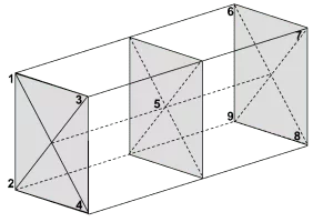
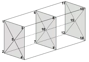
AMS 2750に準拠したTUSを実施する場合、必要なTUSセンサーの数は表11に記 載されています。この数は炉クラスとワークスペースの容積に依存します。AMS 2750仕様ではセンサーの数と設置場所が規定されていますが、熱電対(TC)番号(例:TC 1、TC 2、TC 3)をどこに配置するかはお客様次第です。
以下は、炉クラスとセンサーの総数によるセンサーの配置例である:

3.炉の温度範囲を理解する
1つのファーネスが、ある温度範囲では±10 °F、別の温度範囲では±25 °Fの範囲内で動作することを認定することができる。TUSが、より厳しい温度変化(例:1,500 °Fで±10 °F)に適合することを示した場合、その炉は自動的に、より厳しくない温度変化(例:1,500 °Fで±25 °F)にも適合することになる。
これはAMS 2750仕様に準拠したTUSの場合も同様である。AMS 2750の3.5.2項に記載されているように、「炉は複数の適格動作温度範囲を持つことができる」。
4.ミラー炉パラメータ
TUSのために設定されるパラメーターは、生産時の装置の通常操作を反映することも重要である。つまり、ファンおよび/または分圧を生産時に使用する場合は、TUS時にも使用すべきである。
AMS 2750に準拠する場合、セクション3.5.8に詳細が記載されている。
5.負荷条件の決定
炉のパラメーターは生産中の装置の通常動作を反映する必要がありますが、負荷条件はその例外の一つです。実際の生産負荷、ラック、空の状態などで実施することができます。
これは、3.5.10 項に記載されているように、AMS 2750 でも同様である。「TUS は、実生産負荷、模擬生産負荷、ラック、または空の状態で実施することができる。ただし、使用する負荷条件とTUSセンサーを取り付ける場所に応じて、ヒートシンクおよび/または負荷材料に必要な厚さがある。詳細については、AMS 2750の3.5.10.1項および3.5.10.2項を参照のこと。
6.炉の雰囲気を選ぶ
製造時に使用する雰囲気は何でも、TUS時にも使用すべきである。ただし、以下の場合は空気または不活性ガス (炉の設計に基づく)を使用できる:
- このプロセスでは、テストセンサーを汚染する可能性のある必要な雰囲気を使用する。
- 雰囲気が安全上の危険をもたらす可能性がある
要するに、本番環境がどのようなものであれ、TUSを実行する際には、(指定された例外のいずれかに該当しない限り)可能な限りそれをエミュレートしなければならない。
7.TUSデータ収集の実施
TUSを実施する際には、必要なデータ収集手順に従うことが重要である。AMS 2750に準拠する場合、具体的な要件はセクション3.5.13.3~3.5.13.3.4に記載されている。
全体として、覚えておくべきポイントは以下の通りである:
- 最初のファーネスまたはTUSセンサーが各試験温度の許容下限に達する前にデータ収集を開始する。
- どのセンサーも、温度均一性の許容上限を超えないようにしてください。
- 安定化後、少なくともさらに30分、プラス1分間、データ収集を続ける。
TUSの準備を終えたら、試験荷重(箱、バスケット、治具など)が適切に配置されていることも確認してください。まず、試験荷重を左右の中央に置き、発熱体とワークフェース間の距離が左右で等しくなるようにします。また、試験荷重が正面をまっすぐ向いているか、斜めになっていないか、曲がっていないかを確認してください。
次に、前部と後部のTCの発熱体に対する視野が等しいことを確認する。例えば、フロントTCが発熱体間のエアギャップを見るなら、リアTCもエアギャップを見るべきである。または、前部TCが発熱体の上部から1インチを見ている場合、後部TCも同じように見ている必要があります。
最後に、作業負荷の正確な位置を確定し終えたら、ドレメル工具や弓のこなどを使って作業グリッドに印をつける。この印は、その後の調査において、作業負荷を正確に配置するのに役立ちます。
また、ジャックパネルの経年劣化や状態を常に考慮することも重要である。年以上経過していたり、目視で劣化の兆候が見られる場合は、調査を行う前に交換すべきである。なぜなら、古いジャックパネルや摩耗したジャックパネルは、温度測定値に誤差を生じさせるからである。
結局のところ、機器のバリデーションを適切に行うことは、均一性、信頼性、そして最も重要なことである再現性を確保することにつながります。当社のブログでは、機器のバリデーションに役立つその他のヒントも提供しています。 PIDチューニング そして DigiTrimコントロールで厳しい温度公差を維持.