Temperature Uniformity Surveys (TUS) can be somewhat of a daunting process. After all, a TUS carries the weight of not only being necessary for validating your equipment, but also being required for those that adhere to AMS 2750.

How often you perform a TUS depends on the specifications you subscribe to and the overall performance of your furnace. Typically, a TUS should be performed prior to the first use of a furnace, as well as no less than twice a year, regardless of whether or not you adhere to certain specifications. For those that do adhere to stricter specifications, such as AMS 2750, you should always refer to them for your specific TUS requirements.
Half the battle of performing a TUS is preparation. To aid in that process, we have laid out seven simple steps that are instrumental in helping your TUS efforts go smoothly:
1. Determine the Temperature Uniformity Range
The first step in preparing for a TUS is making sure your furnace is capable of meeting the temperature uniformity range needed for your specific parts and processes. If this is your first time performing a TUS on the furnace, we recommend referring to your OEM specifications to verify that your furnace is performing according to its design classification.
If you are performing a TUS in adherence to AMS 2750, you should determine what the design capabilities of your furnace are and to which furnace classification level you are going to test.
Vacuum furnace systems are classified into six categories: Class One through Class Six. Class One has the most stringent temperature requirements with the smallest allowable deviation in temperature uniformity, while Class Six applies the least restrictive temperature requirements and the widest allowable deviation in temperature uniformity. The range of temperature uniformity varies from ±5 °F (±3 °C) to ±50 °F (±28 °C).
It is also important to note that while many manufacturers claim to be AMS 2750 compliant, there are actually several different versions that constitute compliance in regard to vacuum heat treatment systems. As such, it is imperative that you know the process for which you need compliance so you can ensure the furnace classification meets the specifications.
2. Select Number of Sensors
The size of the furnace, as well as the temperature uniformity you are trying to reach for your specific process, can affect the number of TUS sensors that need to be utilized. At Ipsen, we recommend that wherever you decide to place the thermocouples, you should make it part of the process and train employees who perform the TUS on this process. This will help to reduce any variability that might occur when tuning the equipment for later surveys.
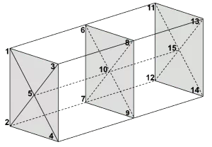
If you are performing a TUS in accordance with AMS 2750, the number of required TUS sensors is mandated in Table 11. This number is dependent on the furnace class, as well the workspace volume. While the AMS 2750 specification mandates the number and geographical location of the sensors, where you place the thermocouple (TC) numbers (e.g., TC 1, TC 2, TC 3) is also up to you.
Below are some example images of how the sensors could be positioned, depending on the furnace class and total number of sensors utilized:


3. Understand Furnace Temperature Ranges
A single furnace can be qualified to operate within ±10 °F at one temperature range, as well as within ±25 °F at another temperature range. If the TUS shows the furnace meets the more stringent temperature variation (e.g., ±10 °F at 1,500 °F), then it also automatically meets the less stringent temperature variation (e.g., ±25 °F at 1,500 °F).
This is also true for a TUS performed according to AMS 2750 specifications. As stated in section 3.5.2 of AMS 2750, “a furnace may have multiple qualified operating temperature ranges.”
4. Mirror Furnace Parameters
It is also important that the parameters set up for the TUS mirror the normal operation of the equipment when it’s in production. This means if fans and/or partial pressure are utilized during production, they should also be utilized during the TUS.
If you adhere to AMS 2750, section 3.5.8 provides further details, as well as a few noted exceptions.
5. Decide on Load Condition
While the furnace parameters should mirror the normal operation of the equipment during production, the load condition is one of the exceptions to that rule. It can be performed with an actual production load, a rack, empty, etc.
This is also true for AMS 2750, as stated in section 3.5.10: “A TUS may be performed with an actual production load, simulated production load, a rack, or empty.” However, dependent on the load condition used and where the TUS sensors are attached, there are required thicknesses for the heat sink and/or load material. Refer to section 3.5.10.1 and 3.5.10.2 in AMS 2750 for additional details.
6. Choose Furnace Atmosphere
Whatever atmosphere you utilize during production should be used during the TUS. However, you can use an atmosphere of air or inert gas (furnace-design specific) if:
- The process uses a required atmosphere that might contaminate the test sensors
- The atmosphere might pose a safety hazard
In short, whatever the production environment is, you must emulate it to the best of your ability (unless it’s one of the specified exceptions) when performing a TUS.
7. Perform TUS Data Collection
When you perform the TUS, it is important to follow the necessary data collection procedures. If you adhere to AMS 2750, specific requirements are laid out in section 3.5.13.3 – 3.5.13.3.4.
Overall, some key points to remember include:
- Start data collection before the first furnace or TUS sensor reaches the lower tolerance limit of each test temperature.
- Do not let any sensors exceed the upper temperature uniformity tolerance.
- Continue data collection for at least an additional 30 minutes after stabilization, plus one minute.
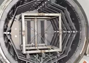
As you finish preparing for the TUS, you should also make sure your test load (e.g., box, basket, fixture) is properly placed. To start, center your test load left to right so that the distance between the heating elements and workface are equal on each side. Also, check the test load to make sure it is facing the front straight on and is not slanted or crooked.
Next, ensure the front and rear TCs’ view of the heating element is equal. For example, if the front TC is looking at an air gap between the heating elements, then the rear TC should also be looking at an air gap. Or, if the front TC is looking at one inch from the top of a heating element, so should the rear element.
Finally, once you have finished establishing the work load’s exact position, mark the work grid with a dremel tool, hacksaw, etc. These marks will help you accurately place the work load for subsequent surveys.
It is also important to always take into consideration the age and condition of the jack panel. If it is older than two years or showing visual signs of degradation, it should be replaced before performing the survey. This is because an older or worn jack panel will cause errors in the temperature readings.
In the end, properly validating your equipment helps ensure uniformity, reliability and – most importantly – repeatability. Our blog also offers other helpful tips for validating your equipment, including a simple breakdown of PID tuning and how to maintain tight temperature tolerances with your DigiTrim controls.
